英语原文共 3 页,剩余内容已隐藏,支付完成后下载完整资料
|
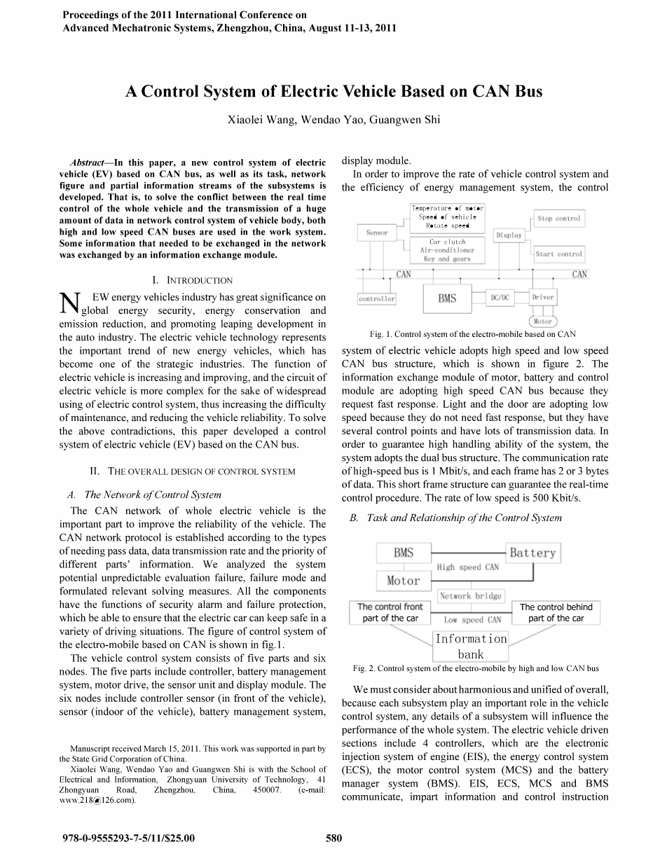
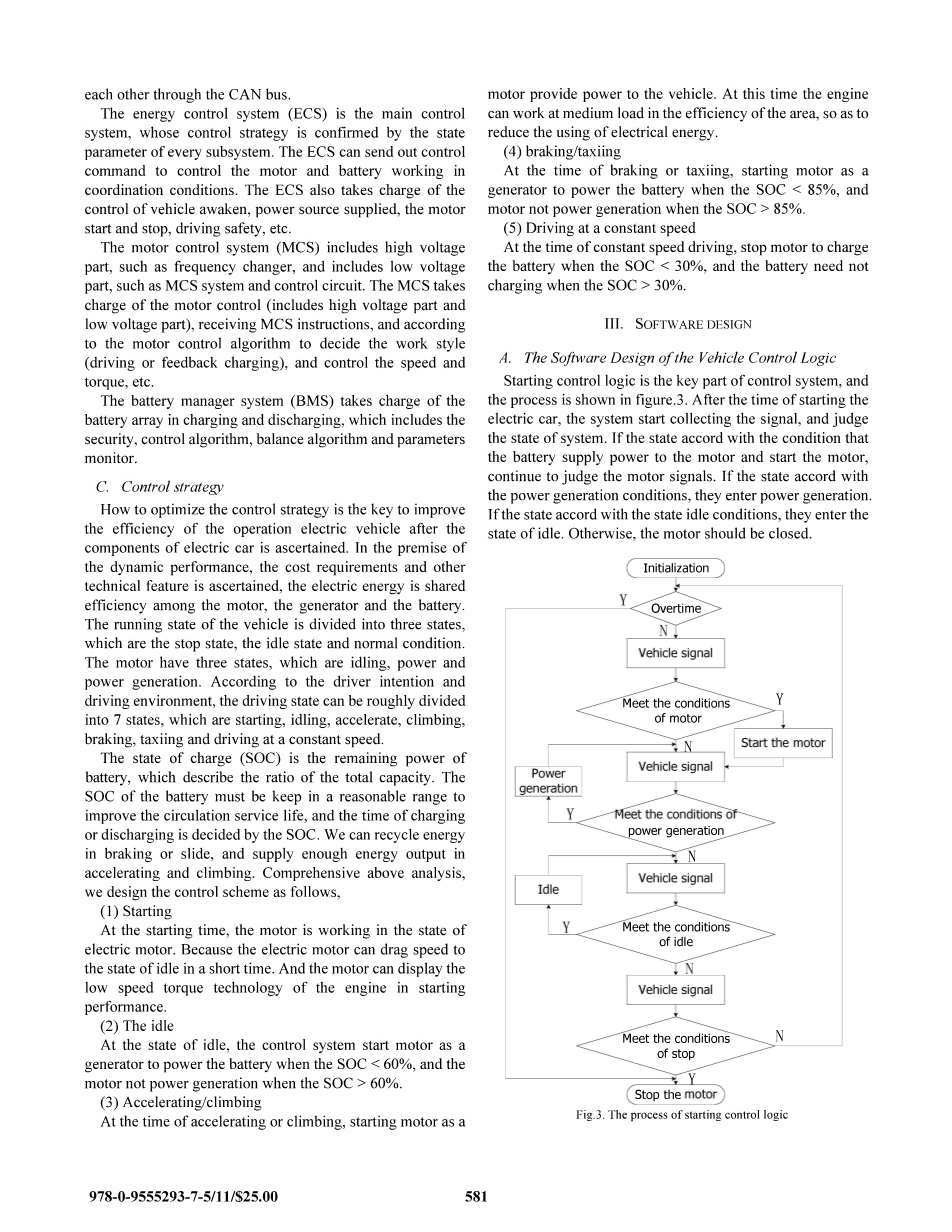
A Control System of Electric Vehicle Based on CAN Bus Abstract:In this paper, a new control system of electric vehicle (EV) based on CAN bus, as well as its task, network figure and partial information streams of the subsystems is developed. That is, to solve the conflict between the real time control of the whole vehicle and the transmission of a huge amount of data in network control system of vehicle body, both high and low speed CAN buses are used in the work system. Some information that needed to be exchanged in the network was exchanged by an information exchange module. I. INTRODUCTION NEW energy vehicles industry has great significance on global energy security, energy conservation and emission reduction, and promoting leaping development in the auto industry. The electric vehicle technology represents the important trend of new energy vehicles, which has become one of the strategic industries. The function of electric vehicle is increasing and improving, and the circuit of electric vehicle is more complex for the sake of widespread using of electric control system, thus increasing the difficulty of maintenance, and reducing the vehicle reliability. To solve the above contradictions, this paper developed a control system of electric vehicle (EV) based on the CAN bus. II. THE OVERALL DESIGN OF CONTROL SYSTEM A. The Network of Control System The CAN network of whole electric vehicle is the important part to improve the reliability of the vehicle. The CAN network protocol is established according to the types of needing pass data, data transmission rate and the priority of different parts information. We analyzed the system potential unpredictable evaluation failure, failure mode and formulated relevant solving measures. All the components have the functions of security alarm and failure protection, which be able to ensure that the electric car can keep safe in a variety of driving situations. The figure of control system of the electro-mobile based on CAN is shown in fig.I. The vehicle control system consists of five parts and six nodes. The five parts include controller, battery management system, motor drive, the sensor unit and display module. The six nodes include controller sensor (in front of the vehicle), sensor (indoor of the vehicle), battery management system,display module. In order to improve the rate of vehicle control system and the efficiency of energy management system, the control system of electric vehicle adopts high speed and low speed CAN bus structure, which is shown in figure 2. The information exchange module of motor, battery and control module are adopting high speed CAN bus because they request fast response. Light and the door are adopting low speed because they do not need fast response, but they have several control points and have lots of transmission data. In order to guarantee high handling ability of the system, the system adopts the dual bus structure. The communication rate of high-speed bus is I Mbit/s, and each frame has 2 or 3 bytes of data. This short frame structure can guarantee the real-time control procedure. The rate of low speed is 500 Kbit/s. B. Task and Relationship of the Control System We must consider about harmonious and unified of overall, because each subsystem play an important role in the vehicle control system, any details of a subsystem will influence the performance of the whole system. The electric vehicle driven sections include 4 controllers, which are the electronic injection system of engine (EIS), the energy control system (ECS), the motor control system (MCS) and the battery manager system (BMS). EIS, ECS, MCS and BMS communicate, impart information and control instruction each other through the CAN bus. The energy control system (ECS) is the main control system, whose control strategy is confIrmed by the state parameter of every subsystem. The ECS can send out control command to control the motor and battery working in coordination conditions. The ECS also takes charge of the control of vehicle awaken, power source supplied, the motor start and stop, driving safety, etc. The motor control system (MCS) includes high voltage part, such as frequency changer, and includes low voltage part, such as MCS system and control circuit. The MCS takes charge of the motor control (includes high voltage part and low voltage part), receiving MCS instructions, and according to the motor control algorithm to decide the work style (driving or feedback charging), and control the speed and torque, etc. The battery manager system (BMS) takes charge of the battery array in charging and discharging, which includes the security, control algorithm, balance algorithm and parameters monitor. C. Control strategy How to optimize the control strategy is the key to improve the effIciency of the operation electric vehicle after the components of electric car is ascertained. In the premise of the dynamic performance, the cost requirements and other technical feature is ascertained, the electric energy is shared efficiency among the motor, the generator and the battery. The running state of the vehicle is divided into three states, which are the stop state, the idle state and normal condition. The motor have three states, which are idling, power and power generation. According to the driver intention and driving environment, the driving state can be roughly divided into 7 states, which are starting, idling, accelerate, climbing, braking, taxiing and driving at a constant speed. The state of charge (SOC) is the remaining power of battery, which describe the ratio of the total capacity. The SOC of the battery must be keep in a reasonable range to improve the circulation service life, and the time of charging or discharging is decided by the SOC. We can recycle energy in braking or slide, and 剩余内容已隐藏,支付完成后下载完整资料 资料编号:[148596],资料为PDF文档或Word文档,PDF文档可免费转换为Word |
课题毕业论文、开题报告、任务书、外文翻译、程序设计、图纸设计等资料可联系客服协助查找。
您可能感兴趣的文章
- 饮用水微生物群:一个全面的时空研究,以监测巴黎供水系统的水质外文翻译资料
- 步进电机控制和摩擦模型对复杂机械系统精确定位的影响外文翻译资料
- 具有温湿度控制的开式阴极PEM燃料电池性能的提升外文翻译资料
- 警报定时系统对驾驶员行为的影响:调查驾驶员信任的差异以及根据警报定时对警报的响应外文翻译资料
- 门禁系统的零知识认证解决方案外文翻译资料
- 车辆废气及室外环境中悬浮微粒中有机磷的含量—-个案研究外文翻译资料
- ZigBee协议对城市风力涡轮机的无线监控: 支持应用软件和传感器模块外文翻译资料
- ZigBee系统在医疗保健中提供位置信息和传感器数据传输的方案外文翻译资料
- 基于PLC的模糊控制器在污水处理系统中的应用外文翻译资料
- 光伏并联最大功率点跟踪系统独立应用程序外文翻译资料